Digital Cave Compass αI Rev C
Components:
- Arduino Micro (Link)
- LSM303DLHC on Breakout Board (Link)
- 8x2 LCD Character Display (Link)
- Protoboard (Link)
- LiPo charging and conversion module (Link)
- LiPo battery (Link)
- Laser Pointer (Link)
- Buttons (Link)
- Assorted Wires, Resistors, Diodes, and Capacitors (See schematic below. Most hobbyists will have on hand)
- Plexiglass (Link)
- Aluminum Standoffs (NON-MAGNETIC!!!] (Link)
- Glue (Link)
- USB to USB Micro Cable (Link) [*Note: USB cable must have data capability. Not just a charging cable.]
- LSM303 Arduino Library (Link)
- Arduino Sketch Environment (Link)
- 10k potentiomer
Description:
This purpose of this update was to take the project from the breadboard stage to the protoboard testing stage. The hardware schematic was updated with lessons learned, and the code was entirely re-written.
Hardware Changes:
Software Changes:
This purpose of this update was to take the project from the breadboard stage to the protoboard testing stage. The hardware schematic was updated with lessons learned, and the code was entirely re-written.
Hardware Changes:
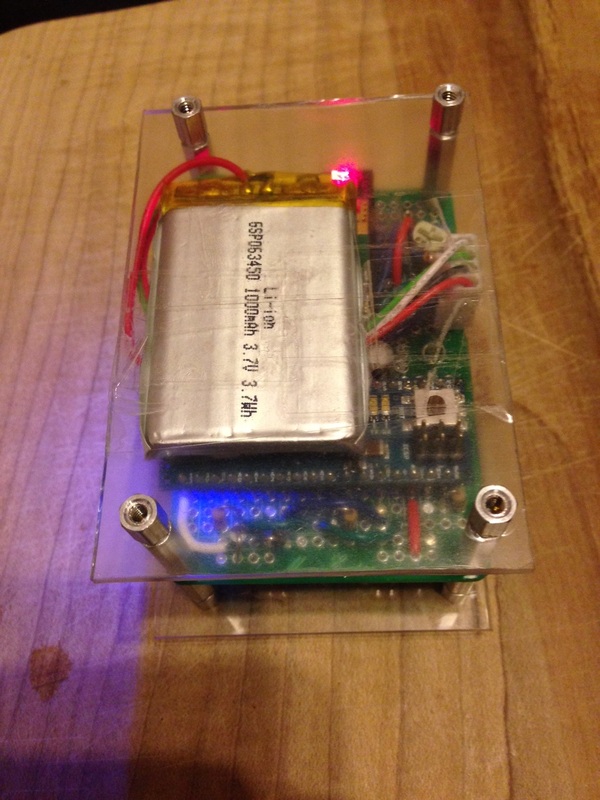
- Add 3.7V LiPo battery and circuitry for charging / voltage conversion.
- Put the hardware on a hardwired protoboard.
- Change the display to a 8x2 LCD in order to fit on handheld protoboard.
- Add 3 pushbutton inputs.
- Add laser pointer.
- Add covers so you can hold the project without touching the electronics
Software Changes:
- LSM303 library is only used to control LSM303DLHC, calculations are now done in a subroutine of the main program. This was done in order to make it easier for others to implement my results while using the current LSM303 library from GitHub without any modifications for float variables.
- Added digitalSmooth filter to all raw data inputs.
- Added offset and scale correction to main file for both magnetometer and accelerometer.
- Added calc_heading function to main file.
- Added calc_pitch_roll function to main file.
- Added interface for using buttons to control device (on falling edge).
- Added debounce to the button inputs
- Added PWM to control output of the laser pointer.
- Added magnetometer calibration routine.
- Added accelerometer calibration routine.
- Added function to save / retrieve calibration values in long term storage on chip.
Hardware Build:
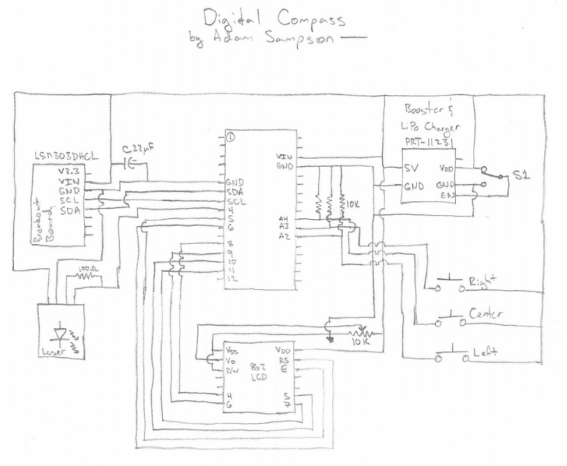
The first steps taken were to prepare the design to be put on the proto-board. To this end I updated the schematic to include buttons and the laser connections.
The first steps taken were to prepare the design to be put on the proto-board. To this end I updated the schematic to include buttons and the laser connections.
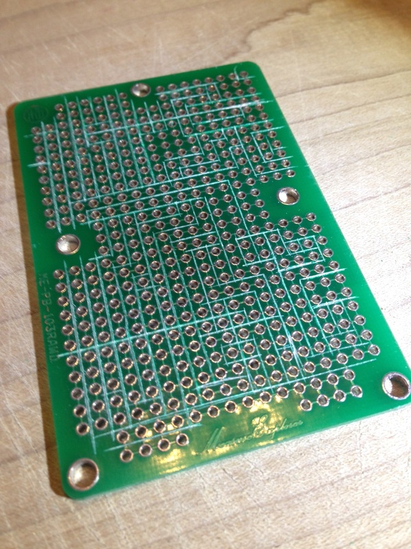
Next I prepared a diagram to indicate which wires on the protoboard my project would use, and which to cut. The diagram also shows where parts will be placed and where jumper wires will be soldered in.
| grid_with_compass_layout_2d.xlsx |
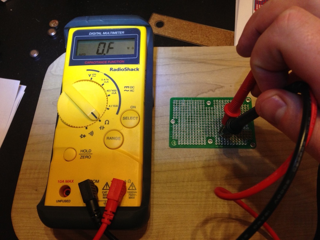
Due to the fact that my project is densely populated with pre-fabricated components, many of them overlap and cover the soldering points for other components. I first placed and soldered the parts that would not interfere with any other components. These included switches, resistors, capacitors, laser header, etc. Next I placed all my components in the metal vias and powered on the project to verify I didn't have any erroneous connections before soldering in my more expensive components.
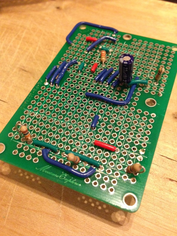
After verifying my connections I went on to solder the next level of nested components. This included the LSM303 chip and the LiPo charger / regulator.
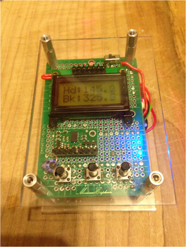
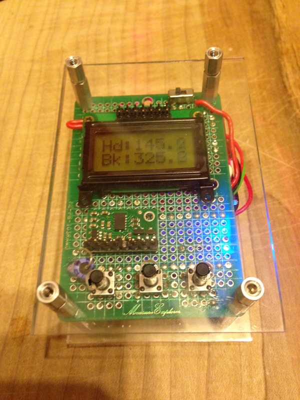
Then I soldered in the Arduino Micro. Finally I soldered in the LCD display which covers half of my breadboard when installed.
Software Build
The software build is pretty self explanatory. I used .h files for includes, but avoided editing them as much as possible. I will try to include all the package here that I used so that others can duplicate my results.
The software build is pretty self explanatory. I used .h files for includes, but avoided editing them as much as possible. I will try to include all the package here that I used so that others can duplicate my results.
| digitalcompassa2_2_ino.ino |
| lsm303.zip |
| eepromanything.zip |
| bounce.zip |
Results:
This compass works much better than earlier iterations. Moving the smoothDigital filter to the inputs had a dramatic improvement on the jitter of the output. The compass is now down to under 1 degree jitter. Additionally, the calibration routines for the variables seem to have made a dramatic improvement to the results I am getting out.
This compass works much better than earlier iterations. Moving the smoothDigital filter to the inputs had a dramatic improvement on the jitter of the output. The compass is now down to under 1 degree jitter. Additionally, the calibration routines for the variables seem to have made a dramatic improvement to the results I am getting out.
Next Steps:
- The very next step is to calibrate the device to account for the mechanical variation between the mounted laser and the digital compass chip (LSM303). Until this is updated all my results will be skewed by some unknown amount.
- After that I will get 6 people (3 experienced and 3 inexperienced) to run a compass course repeatedly on multiple days. This course will be compass in inclinometer only and I will have the only set of distance measurements (to eliminate that variable). I will have each run it with my compass, then run it in reverse with a Suunto for comparison. This will help me to determine repeatability and reproducability.
